5 Key Steps to Automatic Transfer Switch Maintenance
If you own a building with an emergency generator power system integrated into its framework, routine automatic transfer switch maintenance is crucial to ensuring that you can utilize said system when you need it most.
Automatic transfer switches monitor voltage levels in a building’s normal source of power, switching over to an emergency source of power when those levels drop below a certain preset threshold. If a particularly nasty storm or rolling blackout knocks out your primary power source, an automatic transfer switch will activate your emergency power system seamlessly and efficiently.
That’s why regular automatic transfer switch maintenance is of vital concern to any property owner with an emergency power system in tow. If an automatic transfer switch isn’t working properly, it will not be able to detect a drop in voltage levels within a primary power source and switch power to a standby generator during an emergency or power outage. This could lead to complete failure for an emergency power system and all sorts of big problems for devices ranging from elevators to critical medical equipment.

Automatic transfer switch maintenance should be conducted on an annual basis, with shorter maintenance intervals recommended if the switch has been utilized regularly before its last maintenance cycle.
We’ve put together this comprehensive overview to aid you in the automatic transfer switch maintenance process to aid you in everything from inspection to operation of the transfer switch unit. Please make doubly sure to completely cut all power sources connected to the unit before performing automatic transfer switch maintenance.
Also, one important note: automatic transfer switch maintenance doesn’t fall under the DIY header. If you’re not qualified or licensed to perform maintenance on an automatic switch, you could end up accidentally damaging your primary and secondary power sources with an improper approach. You could also end up injuring yourself or others. Please be cautious and contact a licensed technician when necessary and applicable.
Table of Contents
Conducting a basic visual and mechanical inspection of an automatic transfer switch
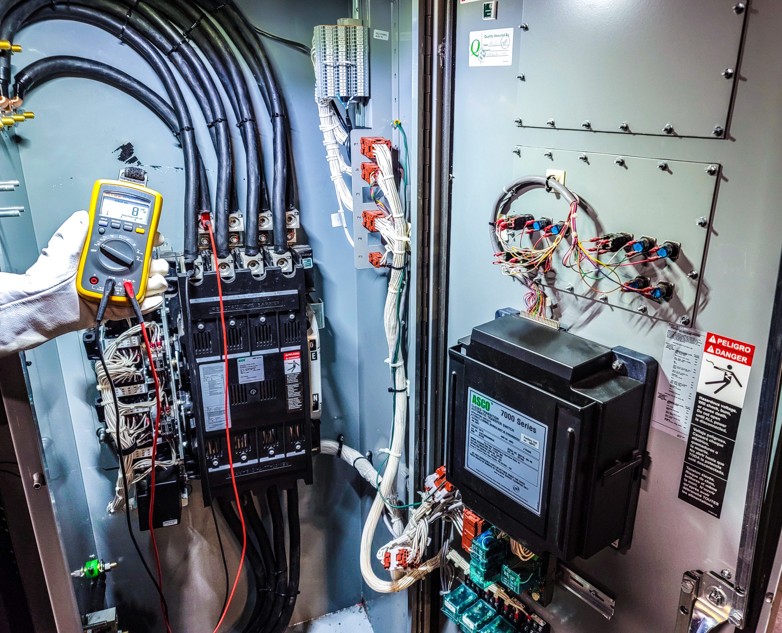
The first step to performing a successful automatic transfer switch maintenance cycle is to cross-reference the information printed on the nameplate of the equipment with the actual system ratings and connections. If the current, voltage, and interrupting differ from the specifications on the nameplate, this could be the sign of a bigger problem. You should also make sure that the correct electrical warning signs and labels are present on the switch, and that the phase rotation, synchronized operation, and phasing are correct and match up to the listed requirements.
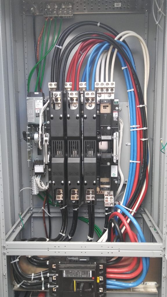
Also, a thorough visual inspection of the full switch is essential when conducting automatic transfer switch maintenance. Double-check all cables for signs of wear and tear. Scan the transfer switch for parts that are not functioning properly, or which have loosened over time.
Make sure no obstructions or potential fire hazards are impeding the utility of the transfer switch. Be diligent and thorough with your visual inspection. Any hazards missed during the transfer switch maintenance process could end up causes for major concern in the case of an emergency.
Key information about cleaning a transfer switch
When cleaning your unit during annual transfer switch maintenance it is imperative to de-energize your transfer switch before cleaning. This should ONLY be performed by a certified technician. In addition, do not use a blower to clear dust and debris from the switch. You could end up shifting the debris deeper into the unit and causing irrevocable damage to your transfer switch. Use a brush with soft bristles or a dry cloth to clear any grime or moisture from the switch, and apply proper lubrication on parts that carry current and moving surfaces if necessary.
To conduct a proper deep clean on a transfer switch, you’ll need to remove the arc chutes or transfer switch barriers so you can take a look at the contacts within. If you see any surface deposits or buildup of dirt and grime, wipe them away immediately with a clean and dry cloth. Make sure the cloth doesn’t have an abrasive edge or surface that could end up damaging the contacts.
The more thorough you are during the cleaning process of your automatic transfer switch maintenance cycle, the better the chances that your transfer switch will operate correctly and efficiently in case of a primary power source outage.
Manually operating a transfer switch for resistance testing
When conducting automatic transfer switch maintenance, its manual operator handle will be quite helpful for identifying problems with the switch’s mechanisms. Since the switch is built to transfer power automatically from a primary power source to a secondary source in case of a drop in voltage, the inclusion of a manual operator handle is helpful because it allows you to test the resistance of your normal power source and emergency power source contacts.
Before using a manual operator handle during the automatic transfer switch maintenance process, be sure to de-energize both your primary power source and your emergency power source. Once this is complete, insert the manual operator handle into the transfer switch and make the manual shift from Normal to Emergency.
If the transfer switch is operating correctly, the switch from Normal to Emergency should be seamless with no binding. Once the test is complete, manually switch the source back to Normal and remove the manual operator handle for storage.
If there are problems with the interlocking mechanisms during manual transfer operation, you’ll need to take a deeper look and potentially look into replacement parts as you continue the automatic transfer switch maintenance process.
Tests to perform during automatic transfer switch maintenance
When performing annual automatic transfer switch maintenance, you should be prepared to conduct a battery of tests on the switch to ensure that it’s in working order. Those tests are as follows:
- Conduct a contact/pole-resistance test to ensure that dc millivolt and microhm drop values do not exceed the highest levels of the normal range dictated by the switch manufacturer. If you can’t find this data in published form, be on the lookout for any values with a 50 percent deviation or more from nearby poles or switches of the same type.
- Inspect all bolted electrical connections with the help of a thermographic survey, low-resistance ohmmeter, or by utilizing the calibrated torque-wrench method. Look for abnormally high resistance and be prepared to look further into any values that are more than 50% of the lowest recorded value. Also, ensure that bolt/torque levels match up with the manufacturer’s published data.
- Complete a variety of automatic transfer tests and observe how the transfer switch operates under the following simulated circumstances; a complete normal power outage, a re-energized normal power source following an outage, a complete loss of emergency power, and single-phase conditions of all types and forms. Investigate any problems and abnormalities as you continue the automatic transfer switch maintenance cycle.
- Complete a variety of timing and operational tests on the transfer switch. These tests should be conducted for the following functions; transfer time delay, engine starting, normal power source frequency-sensing and voltage-sensing relays, emergency power source frequency-sensing and voltage-sensing relays, re-transfer time delay when normal power is restored, automatic transfer functionality, limit switch function, and interlocks, and full engine cool down and shutdown. Please note that all testing values should fall in line with the system and manufacturer’s design specifications. Investigate any problems and abnormalities as you continue automatic transfer switch maintenance.
- Ensure that all control devices for the transfer switch are operating correctly with the correct settings outlined by the manufacturer. Investigate the settings for all connected timers and make any needed adjustments.
- Optional: Conduct insulation-resistance tests for all control wiring in terms of ground. For one minute, apply 1000 volts dc to all 600-volt rated cable and 500 volts dc to all 300-volt rated cable. All insulation-resistance values should be two megohms or more. Compare your findings to results from any previous tests, and investigate any readings under two megohms as soon as possible. Before conducting these tests, you must disconnect and disengage all fuses and plugs for control devices or with solid-state components that are not constructed to handle the test voltage values.
Final notes on performing proper automatic transfer switch maintenance
Following the completion of the automatic transfer switch maintenance process, an NFPA-approved field testing label should be applied to the transfer switch. This indicates that the transfer switch is in proper working order from a mechanical and electrical standpoint.
Annual transfer switch checkups are an important part of properly maintaining an emergency power system for when the unthinkable happens. When you take the time to do it right, the maintenance process can add years to the utility of a transfer switch while ensuring the safety and well-being of those working and living on the property it services.